Bison Versadjust Pedestal Installation Guide

bison pedestals installation guide
The Bison Versadjust (V-Series) Adjustable Pedestal line has a broad footprint that provides stability, is impervious to freeze thaw cycles, and offers a range of heights suited to a wide variety of applications. Precise spacer tabs allow for deck drainage and uniform paver spacing, while the screw-to-adjust height settings assure a perfectly level deck. The Bison Versadjust Pedestal series reaches heights from 2-1/4” to 36” (57 to 914 mm), has a weight bearing capacity of 1250 lbs (FoS:3), and contains built-in slope compensation for 0” to 1/2” per foot slope (0 to 4%). Accessories are available to compensate for additional slope (up to 1” per foot or 8%) and accomodate low height applications from 1/8” to 2-1/4” (3.2 to 57 mm). Quick Clip Couplers increase the speed and effi ciency of installing pedestals at heights over 9” (229 mm). Use Versadjust Pedestals with the Bison Brace System for excess height installations from 24” to 36” (610 to 914 mm) or for installations requiring additional stability. Proudly manufactured in the U.S.A.
VT Spacer Tab
(Specify tab width when ordering) VT316 – 3/16” (4.5 mm) standard VT18 – 1/8” (3.2 mm) optional Place spacer tab on top of pedestal. To remove tabs, strike spacer tabs with hammer on edge.
V-Series Top
Comes screwed into V-Series Base. Unscrew top until thread engagement indicators are felt and heard. DO NOT extend beyond this point except to add a VC2 Quick Clip Coupler to a V4 Pedestal.
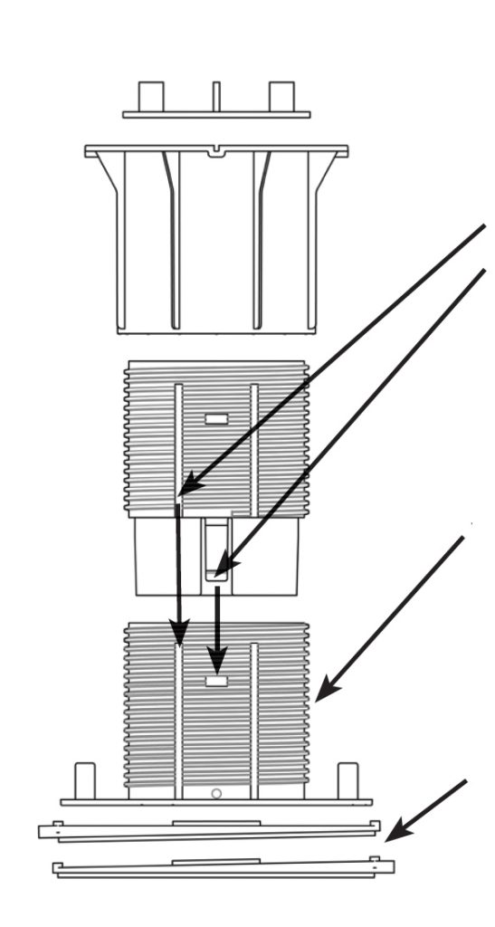
VC2 Quick Clip Coupler (Works with Model V4 only)
To Assemble:
Align lines on coupler and base.
Align tab with quick clip slot.
Slide together until tab locks into place.
To Separate:
Hook VC2 Quick Clip Coupler Release Tool into slots on the side of the pedestal base or coupler, detach tool, and pull apart.
V-Series Base
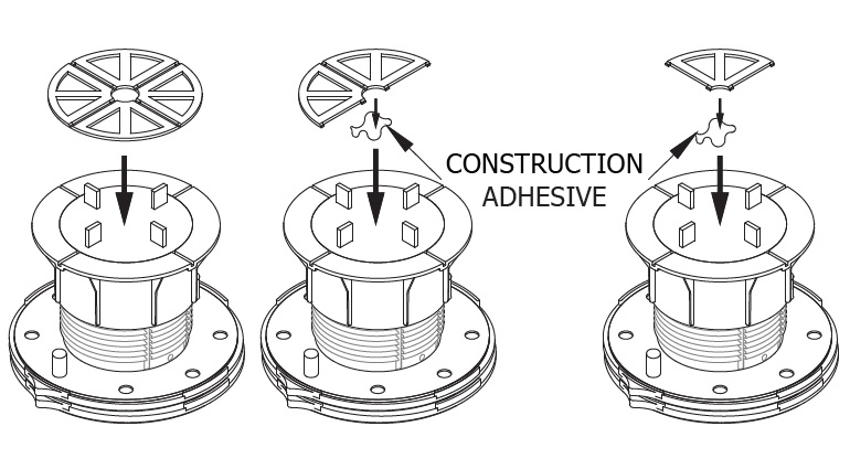
Comes screwed into V-Series Top. Unscrew top until thread engagement indicators are felt and heard. DO NOT extend beyond indicators except to add an VC2 Quick Clip Coupler to a V4 Pedestal.
V-Series Base
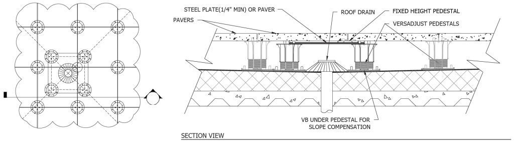
Built-in base leveler provides 0” to 1/2” per foot slope compensation (0 to 4%).
Built-In Slope Compensation

Each V-Series Pedestal comes with a VB Base Leveler that compensates for up to 1/2” per foot slope (4%).

Slope Adjustment:
Point both fi nger tabs downhill for 1/2” per foot slope (4%). Rotate base pieces for precise slope
compensation.

To Create a Flat Base:
Position finger tabs
opposite one another.

AS SHOWN: 2x LD4s COMPENSATING FOR 1/2” PER FOOT SLOPE (4%)

To remove VB Base Leveler, slide pedestal base out of VB Base Leveler.

For additional slope compensation, a maximum of 2 additional LD4 Base Levelers can be used with the V-Series Pedestals adding an additional 1/2” per foot slope (4%) for a total of 1 inch per foot slope (8%). Each LD4 adds 1/4” (6 mm) to the overall height of the pedestal.
IMPORTANT: Refer to Versadjust product specifications to ensure proper use and installation. For more information visit www.bisonip.com.
Advanced Layout and Pedestal Placement
“T” Method Installation

1. Determine cavity heights at all thresholds, drains, and high points.
2. Deduct thickness of decking material.
3. Mark top of pedestal elevation around deck with chalk line or laser level.
4. Plan paver/pedestal layout pattern in advance.
5. Install “T” shaped portion of deck starting from threshold or high point.
6. Adjust to correct height and level.
7. Install on both sides of the “T”.

t method bison pedestal installation
Determining Cavity Height
  • The cavity height is the space between the top of the roofing membrane and the bottom of the decking material.
  • Use a laser level or chalk line to assist.
  • Refer to the detachable measuring device printed on the box.
determining cavity height install bison pedestal
(a)Threshold and (b) Perimeter Placement
  • Use extra pedestals under small cut pieces for additional support.
  • Adhere small pavers to top of pedestal with construction adhesive.
  • Remove tabs as necessary for perimeter pedestals.
  • Turn pedestals upside down or trim pedestal bases as necessary to fit around the perimeter.
  • Decking pavers must not be spaced more than 3/16” (4.5 mm) from the perimeter containment.
  • Adhere tabs into place with construction adhesive to maintain spacing between pavers when normal tab placement is not possible.
threshold and perimeter bison pedestal installation
Radius Placement
  • Use extra pedestals under small cut pieces for additional support.
  • Adhere small pavers to top of pedestal with construction adhesive.
  • Remove tabs as necessary for perimeter pedestals.
  • Turn pedestals upside down or trim pedestal bases as necessary to fit around the perimeter.
  • Decking pavers must not be spaced more than 3/16” (4.5 mm) from the perimeter containment.
  • Adhere tabs into place with construction adhesive to maintain spacing between pavers when normal tab placement is not possible.
radius placement bison pedestal installation guide
a3 deck system components
Low Elevation Placement
For low cavity heights the following pedestals are available:
low elevation placement bison pedestal installation guide
Shims can also be used to accomodate variations in height:
  • 1/16” (1.5 mm) B11 Shim
  • 1/8” (3.2 mm) PS1 Shim
low elevation placement bison pedestal installation example
Diagonal Placement
  • Use extra pedestals under small cut pieces for additional support.
  • Adhere small pavers to top of pedestal with construction adhesive.
  • Remove tabs as necessary for perimeter pedestals.
  • Turn pedestals upside down or trim pedestal bases as necessary to fi t around the perimeter.
  • Decking pavers must not be spaced more than 3/16” (4.5 mm) from the perimeter containment.
  • Adhere tabs into place with construction adhesive to maintain spacing between pavers when normal tab placement is not possible.
bison pedestal installation diagonal placement 2
Drain Placement
  • Elevate a steel plate or spare paver above the drain but below the deck itself.
  • Use that elevated paver to support a pedestal where you need for the deck above.
Working with Wood
JS Joist Saddle

The JS can be used alone or on top of any Bison Pedestal. A screw is included for attachment to adjustable pedestals. It is designed to support 2x joists in one direction and 4x (or staggered 2x) joists in the other direction. Place a joist between the JS walls and attach it with #8 deck screws (NOT provided).

IMPORTANT: Do not overtighten screw when attaching the JS to an adjustable pedestal.
bison pedestal joist
AS SHOWN: JOIST SADDLE WITH 2×4 JOISTS (STAGGERED)
FS-1 Wood Tile Fastening Kit

Place FS-1 washer in the kerf between the surface planks and the runners. Screw FS-1 washer through center hole of spacer tab set and into pedestal.

Make sure that washer clamps all corners of wood tiles and then tighten. To remove a wood tile: Loosen screw, and, using a screwdriver, rotate FS-1 washer to release wood tile.

bison tile fastener
Working with Shims
PS1 1/8” (3.2 mm) Shims – Rigid

PS1s may be placed on top of pedestals to accommodate for minor leveling of pavers with thickness variations. Use no more than 2 shims. If using only quarter segment, adhere it to the pedestal with construction adhesive.

adhering bison rigid shims to pedestal place with construction adhesive
B11 1/16” (1.5 mm) Shims – Flexible

B11s may be placed on top of pedestals to accommodate for minor leveling of pavers with thickness variations. Use no more than 2 shims. If using only quarter segment, adhere it to the pedestal with construction adhesive.

adhering bison shims to pedestal place with construction adhesive
PS1 and B11 Shims Under Pedestals

Place shims (whole or in segments) under the pedestal in a stairstep fashion to compensate for sloping substrates. Use no more than 2 shims. Adhere them to each other and to the pedestal with construction adhesive. IMPORTANT: Do not adhere to substrate.

adhering bison flexible shims in place with construction adhesive
Pedestal Base Pads
Floating Insulation Base (FIB)

The FIB is required beneath Bison Pedestals to disperse the deck load over roofing systems with a compressive resistance of 20 to 40 psi (138 to 275 kPa). The FIB provides a large 12” x 12” (305 x 305mm) base bearing surface. FIBs are not recommended for use with VT or HD25 Fixed Height Pedestals. IMPORTANT: The pedestal must be placed in the center of the FIB for proper installation. The FIB may be trimmed to accommodate narrow perimeter placement if necessary. Trim at least 4.125” away from the center.

floating insulation base fib bison deck support
Floating Foundation Base (FFB)

FFBs are required for use beneath all Bison Pedestal decks installed on-grade (soil). Level the surface and set the FFB directly on-grade as a base below each pedestal.

floating foundation base ffb bison deck support

Maintenance Guide

Routine maintenance of your paver deck system will enhance the beauty, reduce major repairs, and prolong the life of your deck. Below is a list of maintenance guidelines that should be performed on a regular basis:

  1. Check for pavers that rock. If you notice pavers rocking back and forth while walking on the deck, simply lift the paver up and shim one or more corners until the paver is level on all four corners. To ensure pedestal stability, make sure to not exceed the thread engagement indicators. Bison 1/16” (1.5 mm) B11 Shims or 1/8” (3.2 mm) PS1 Shims can be ordered and shipped.
  2. Depending on substrate materials, some settling and/or deflection can occur. Remove the paver and adjust the pedestal until a level height is achieved. You may need to do this to more than one pedestal to level out an area.
  3. Clean drains and scuppers on a regular basis. Water should completely drain off the roof deck within 48 hours after rainfall, under ambient drying conditions. Standing or pooling water can be detrimental to some waterproofing systems.
  4. Periodically check the spacer tabs between pavers, and replace broken spacer tabs immediately. Loss of spacer tabs could create unsafe deck movement.
  5. Make sure the edge restraint remains intact. There should not be room around the perimeter of the deck in excess of 3/16” (4.5 mm) width which would allow for lateral movement of the pavers and create an unsafe condition.
  6. Follow paver manufacturers’ suggestions for upkeep and maintenance of the pavers.